PoE - Why won’t it work?
In the first post we talked about PoE and how great it is; however, there are a couple potential “gotchas.” If you have dealt with PoE, you may have run into a situation where you connect a PSE and PD that both support PoE, but it just does not work. In this post we will first briefly talk about the IEEE PoE standards, then we will be discussing one potential reason why your PSE and PD won’t work with each other: PoE capable vs. PoE compliant.
IEEE Standards
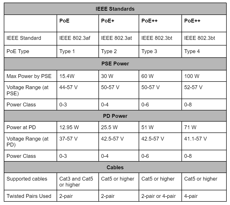
IEEE initially created the 802.3af standard that covers PoE, and continued to expand the standard as PoE power needs have grown over time. Below is a table showing the primary differences. There is a lot to unpack here, which we will cover in another post.
The original 802.3af standard was released in 2003. Since then, 802.3at and 802.3bt have been developed to support higher power demands.
For this discussion, we will be focusing on the original standard, 802.3af.
Capable vs Compliant PD
Let’s say you need to get a bunch of cameras at the plant because someone keeps forgetting to start the machine after lunch. You got the brand new IPCam9000, PoE capable, to catch him in the act! Even better, you don’t have to run extra power wires to all the cameras. Just plug it into the PoE switch and….nothing.
What’s going on? Well, unfortunately even though the PD is capable, and even if you may have a PSE that is IEEE compliant, the possibility still exists the two still won’t match up.
So what’s the difference between capable and compliant?
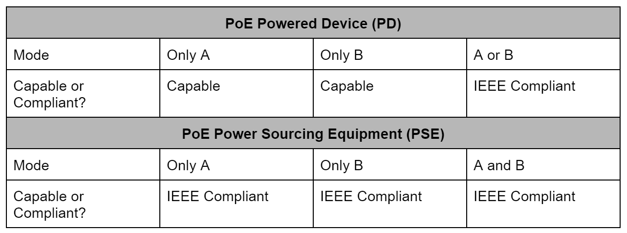
PoE capable means the PD device supports only Mode A or only Mode B.
PoE compliant means the PD device supports both Mode A and Mode B.
Below is a chart showing the difference between capable and compliant.
While a 802.3af compliant PD is required to support both Mode A and Mode B, a PSE can be compliant if it supports Mode A, Mode B, or both Mode A and Mode B.
So what’s all this Mode A and Mode B riff raff? We will explain these terms in the next section, but for now, just know that which modes the device supports determines whether it is capable or compliant.
As you can see, if you have a compliant PD, it will support both Mode A and Mode B. So even if your PSE only supports only A or B, the devices will work together.
Mode A vs. Mode B
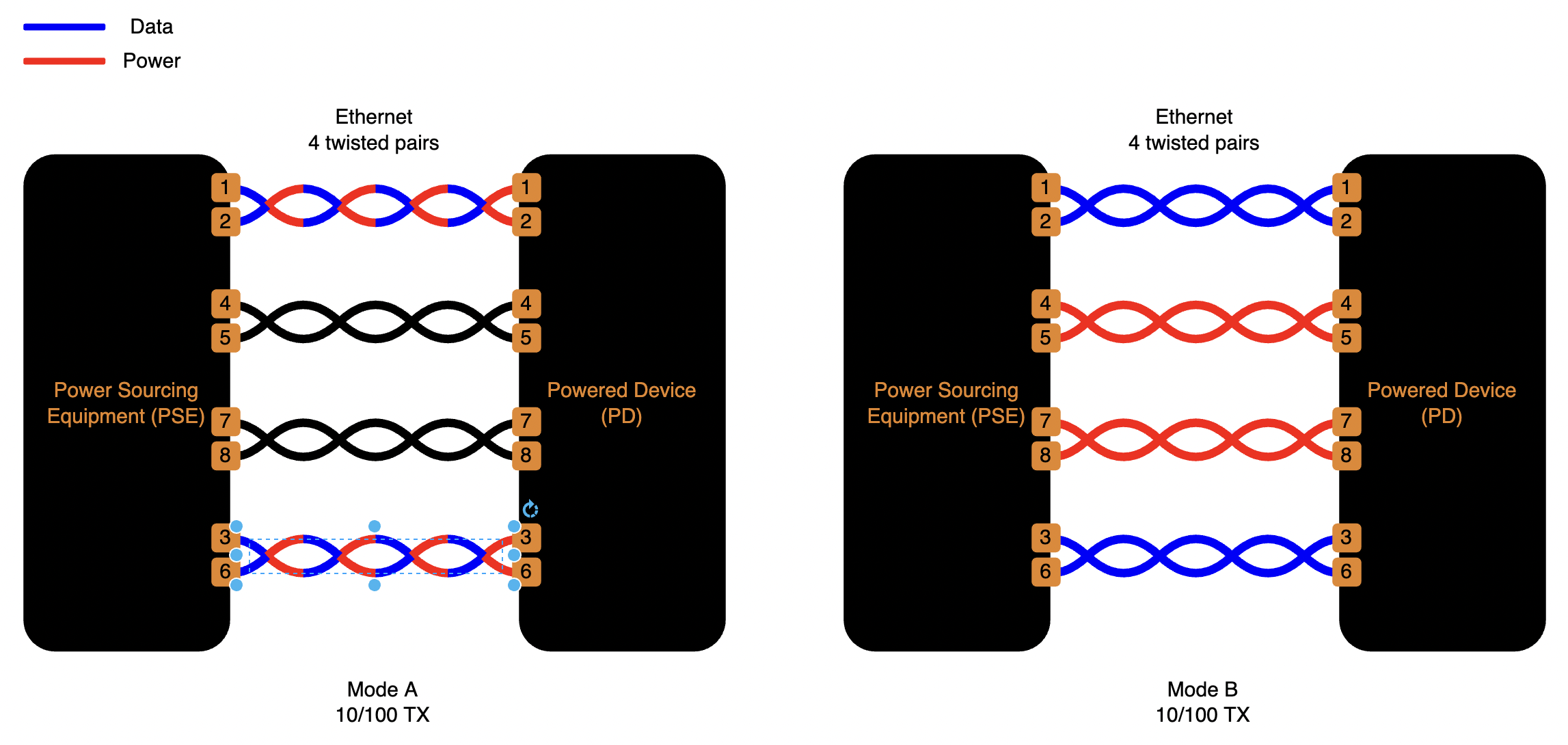
The 802.3af standard describes two different modes for powering 10/100 TX devices, Mode A and Mode B. An ethernet cable has 4 twisted pairs. The difference between Mode A and Mode B are in what wire pairs power is supplied.
Mode A supplies power on the same twisted pairs as the data.
Mode B supplies power on the spare twisted pairs.
IEEE 802.3af compliant devices (active) are smart enough to only supply power if the device requests it.
Endspan vs. Midspan PSE
A Mode A PSE is also known as an endspan device and a Mode B PSE is also known as a midspan device, which describes the position in the system of where the power is coming from. A PoE switch would be endspan, and a PoE injector would be midspan.
So, putting it all together:
There are PoE capable and PoE compliant PD devices.
Capable PDs won’t necessarily support both Mode A and Mode B.
Compliant PDs will support both Mode A and Mode B.
Endspan PSE support Mode A.
Midspan PSE support Mode B.
How about about some real world examples?
A customer had a PoE-capable Ethernet/IP Rotary Shaft Encoder, but closer datasheet inspection revealed it was not 802.3af compliant. As it turned out, this was only a 4-wire, or two twisted pair device. This means the power has to be transmitted on the same wires as the data (Mode A). This would not work with the customer’s Mode B PSE. We supplied a Mode A PSE and resolved the issue.
But datasheets will save us, right? RIGHT?!
We can see from the above example that it is important to review datasheets for PoE devices.
BUT…
Unfortunately we have observed some vendors' documentation do not state which mode their devices utilize, which makes it challenging to avoid compatibility issues.
ALSO…
Once we came across a vendor's PoE switch whose series datasheet listed Mode A and Mode B, offered two part numbers ending in A and B with PoE Mode as the only difference between the two. Only upon close inspection did we notice the A part number utilized Mode B and the B part number utilized Mode A.
Crazy enough? Stick with us. In the next post, we will talk about another pitfall related to PoE: passive vs. active.


